Sensor setup
Dec 31, 2014
Assembly options and sensor setup
The sensor firmware can be used with different configurations. Basically the firmeware should be able to support different revisions of the sensor, several assembly options and be configurable to different models and flight situations.
Assembly options
REV_B as the actual sensor can be assembled with different component options. The
Allegro ACS758LCB-100U-PFF-T is as well available in a 50A and 200A version.
This indicates the maximum measurement range of the hall sensor, while
it can take a current many times higher without damage. But using the 50A version
will give double the precision than the 100A version.
By changing the resistors (R7 and R8) of the voltage divider for the voltage measurement, batteries with more than 6 cells can be supported as well as higher precision for less cells can be enabled.
Another option is to omit the Bosch BMP180 pressure sensor, if the altimeter and vario
functions are not needed. Unused connectors can be cut out as well.
Firmeware setup
One basic requirement is to setup the capacity of the used battery for the alarm.
While it is no problem to setup the sensor using the development environment, a target of
the project was to provide setup methods not requiring a development environment. The
hardware offers two general possibilities. One option is to use the Serial port via a
Serial-USB adaptor or a PC independent setup box. The second is to use the build
in button. The latter method can only provide basic setup functions.
Setup parameters
Here is a list of useful setup parameters:
- Capacity of the sensor in mAh
- Alarm threshold at a minimum capacity (in mAh) or as a percentage left of the max capacity (in %)
- An optional second alarm threshold for the capacity (as the Powerbox sensor has two capacity alarms
- A voltage threshold for the main battery voltage (in mV) or,
- The number of cells used and a calculated minimum voltage of the pack
- The hight of the airfield (in m), useful, if the flight can go below the airfield (in the mountains)
- Several calibration parameters to adjust the sensor to the used components
Setup on the airfield
The setup method for the airfield using the sensors button, allows only for setting up the Capacity of the battery in mAh. The alarm (Cap1 alarm) will be activated, if the calculated capacity falls under 20% of this value.
For the setup start the transmitter with the model setup bound to the receiver used and the Powerbox telemetry sensor activated. Now hold the button on the bottom side (backside of the XMEGA) pressed while powering the sensor. Note that the power for the sensor comes via the X-Bus, TM1000 and receiver from the receiver battery or BEC. The sensor will indicate the setup mode by blinking three times both LEDs. Release the button after the first blinking of both LEDs.
Now the Cap1 display will count up by one hundred each second starting by zero again. If the desired number is displayed press the button until the red LED goes out. Now the display will loop through the thousands digit from 0 to 9. If the right number is displayed press the button until the red LED lights up again. Now the same process starts for the ten thousands digit, but only from 0 to 5. Press the button until the red LED lights up.
If the value is saved successfully to the EEPROM, the red LED goes out again. The sensor can be used right away and will reload the stored capacity value on the next power up.
To stop the setup process in between, cut the power of the sensor!
Self calibration
Since the ACS758 hall sensor and ADC have some tolerance, as well as the used resistors a calibration procedure is required. After the setup procedure, the sensor will do a self calibration. Please make sure, that nothing is connected to the battery cables. The sensor will get it’s power via the X-Bus from the TM1000 module. The calibration values are stored to the EEPROM as well.
Restrictions
I implemented the setup function using a simple way. There are no interrupts, no debounce of the button, etc. So you need to watch to the LED and release the button after the red light changes. But hey, it is only the setup function, you won’t use it every day.
Since the capacity in the Spektrum X-Bus protocol uses a 16Bit variable, the maximum is 65535mAh. For program simplicity the maximum battery capacity is now limited to 59.900mAh, which should be good enough for most RC use cases.
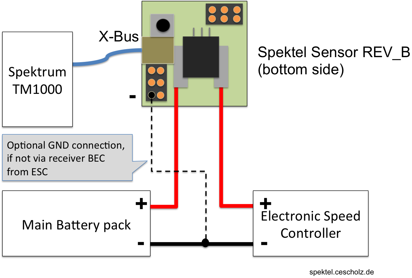
Hook up diagramm
Since I have not given a hook up guide, I will provide a small sketch to see the basic installation. To measure the main battery voltage, there needs to be a ground connection between the sensor and the main battery negative pole. This is normally given by the BEC system in the electronic speed controller. If not you need to wire an additional connection.
Outlook
The serial port was intended to provide more sophisticated options for setting up the sensor. Using a terminal program and a kind of AT commands this can be easily achieved.
Share