XMEGA, ASF and TWI/I2C
Jan 03, 2015
Getting TWI and I2C running with the Atmel ASF and XMEGA
One of the main XMEGA features the sensor uses is the I2C (Inter-Integrated Circut) or TWI
(Two-Wire-Interface) serial data bus. It is used for the Spektrum RC Telemetry X-Bus as
a Slave and for the Bosch BMP180 pressure sensor as a Master. In both cases the XMEGA
hardware capabilities are used.
While the first prototyping with an Arduino was quite simple, it took me some time to figure things out using the XMEGA and ASF (Atmel Software Framework). In my opinion it is because the XMEGA is far less used by makers and hobbyists compared to the ATMEGA series. And the ASF functions have some undocumented unexpected behaviour. The main source I used have been the XMEGA datasheet and AFS Quickstart examples, which you can find on the Atmel website and at the end of some library header files as comments.
I will try to give an overview, pitfalls and solutions in this article. May it help others to save some time.
XMEGA TWI Bridge Mode
The ATXMEGA32E5 offers a feature called Bridge mode. And I didn’t found much help on this.
If you go to the ATXMEGA32E5 datasheet it lists the following Alternate Pin Functions
(in chapter 32.2) for TWI:
- PORT C - PC0 (Pin 16) - SDA
- PORT C - PC1 (Pin 15) - SCL
- PORT D - PD0 (Pin 28) - SDA (TWID (Bridge))
- PORT D - PD1 (Pin 27) - SCL (TWID (Bridge))
Chapter 22 of the Atmel datasheet gives some more hints:
- Bridge mode with independent and simultaneous master and slave operation
- Independent timeout counters in master and slave (Bridge mode support)
- By using the bridge option, the slave can be mapped to different pin locations
- The master and slave can support 100kHz, 400kHz and 1MHz bus frequency
- It is also possible to enable the bridge mode. In this mode, the slave I/O pins are selected from an alternative port, enabling independent and simultaneous master and slave operation
- PORTC has one TWI. Notation of this peripheral is TWIC
- Alternative TWI Slave location in bridge mode is on PORTD
Chapter 18 of the Atmel ATXMEGA Guide adds the following:
“When enabling the bridge mode, both master and slave can be active at the same time, each with its specific IO pins. Refer to the device datasheet to see which actual I/O port is used as alternative port selection for the slave in bridge mode.”
Following this we have to use Port D as TWI slave and PORT C as TWI master.
So the setup look like the following:
conf_board.h
 1 //Part of conf_board.h
 2 // TWIM for BMP180
 3 #define TWI_MASTER       TWIC
 4 #define TWI_MASTER_PORT  PORTC
 5 #define TWI_MASTER_ADDR  0xEF
 6 #define TWI_SPEED        1000000
 7
 8 // TWIS for XBUS
 9 #define TWI_SLAVE        TWIC
10 #define TWI_SLAVE_PORT  PORTD
conf_twim.h looks like this:
1 #define CONF_TWIM_INTLVL        TWI_MASTER_INTLVL_MED_gc
2 #define CONF_PMIC_INTLVL        PMIC_MEDLVLEN_bm
In the sensor coding, the TWI initialization code is in the spektel.c file:
 1 bool spektel_init() { //TWI_t *twis) {
 2 // Initialize ports
 3 TWI_MASTER_PORT.PIN0CTRL = PORT_OPC_WIREDAND_gc;
 4 TWI_MASTER_PORT.PIN1CTRL = PORT_OPC_WIREDAND_gc;
 5
 6 irq_initialize_vectors();
 7
 8 sysclk_enable_peripheral_clock(&TWI_MASTER);
 9
10 twi_bridge_enable(&TWI_MASTER);
11 //twi_fast_mode_enable(&TWI_MASTER);
12 //twi_slave_fast_mode_enable(&TWI_SLAVE);
13
14 twi_options_t m_options = {
15 	.speed     = TWI_SPEED,
16 	.chip      = TWI_MASTER_ADDR,
17 	.speed_reg = TWI_BAUD(sysclk_get_cpu_hz(), TWI_SPEED)
18 };
As you can see the bridge mode works without the fast modes.
Make sure you call sysclk_init(); at the beginning of your code and change conf_clock.h
to the desired clock speed.
Initializing the master:
1 status_code = twi_master_init(&TWI_MASTER, &m_options);
2 if(status_code != STATUS_OK) printf("spektel_init.twi_master_init status: %x", status_code);
3 twi_master_enable(&TWI_MASTER);
TWI X-Bus slave initialization
We need to calculate the TWI slave address, the XMEGA TWI hardware implementation listens to. The TWI master always sends a 7-bit slave address to address one slave listening on the bus. There is a register for this address, but in our case the sensor should behave like a multiple personality and react to three sensor addresses.
As muknukem (am rcgroups.com and rc-heli.de forums member) re-engineered, the Spektrum RC X-Bus starts to enumerates the sensor addresses 70ms after the power is stable. It sends a request for each address between 0x01 to 0x7D, with pauses of 13ms in two cycles. Each sensor the Spektrum transmitters know have one or more (the GPS sensor uses two, because it needs to send more data) addresses. So the number of different sensors is theoretically limited by the number of the requested addresses. On the other hand all is fixed and simple.
The good thing is, the TM1000 telemetry module doesn’t care, if the sensor reacts to a request for lets say address 0x01 with 0x0A for the Powerbox sensor. It uses what the sensor sends back. After the startup procedure, the TM1000 only asks for sensors we sent a response for (again, the address sent back is the interesting one).
The XMEGA reacts to all addresses by setting this register:
1 TWIC.SLAVE.CTRLA |= 0x02; // PMEN: Promiscuous Mode Enable - address match logic disabled, react to everythingBut to save the interrupt routines some work it could be useful to set the XMEGA hardware to react not to all. On the ATMEGA and Arduinos the following code works:
 1 uint8_t twi_slave_address = 0x00;
 2 status_code_t status_code = 0x00;
 3 // calculate slave address for single sensor (two TWI addresses are only support by XMEGA)
 4 if( CURRENT_TEL ) {
 5 	twi_slave_address |= CURRENT_SENS;
 6 }
 7 if( POWERBOX_TEL ) {
 8 	twi_slave_address |= POWERBOX_SENS;
 9 }
10 if( VARIO_TEL ) {
11 	twi_slave_address |= VARIO_SENS;
12 }
In my experience, this is not working for the XMEGA! And two addresses can be applied with respect to the datasheet, but not three.
So the further code looks like this:
1 sysclk_enable_peripheral_clock(&TWI_SLAVE);
2 TWI_SlaveInitializeDriver(&slave, &TWI_SLAVE, *slave_process);
Where *slave_process is a pointer to the a function reacting on requests from the master.
I will get into more detail later on.
1 TWI_SlaveInitializeModule(&slave, twi_slave_address, TWI_SLAVE_INTLVL_MED_gc);
2
3 //TWI address for Current, Powerbox and Vario and flight pack capacity
4 TWIC.SLAVE.ADDRMASK = (0x7F << 1) ;  //mask (1) all address bits, which are different between all used sensors
5
6 for (uint8_t i = 0; i < TWIS_SEND_BUFFER_SIZE; i++) {
7 	slave.receivedData[i] = 0;
8 }
The magic is done by writing 0x7F to the upper 7bits of the Slave ADDRMASK Address Mask Register. The datasheet says:
“If ADDREN is set to zero, ADDRMASK can be loaded with a 7-bit slave address mask. Each bit in ADDRMASK can mask (disable) the corresponding address bit in the ADDR register. If the mask bit is one, the address match between the incoming address bit and the corresponding bit in ADDR is ignored; i.e., masked bits will always match.”
We leave ADDREN (Bit 0 of the same register) to zero. The mask is calculated as following:
1 0000 0011	Current Sensor address
2 0000 1010	Powerbox Sensor address
3 0100 0000   Vario Sensor address
4 0011 0100   Flight Pack Capacity Sensor address
5 -----------------------------------
6 0111 1111   = 0x7F as Address Mask
EDIT: With the new Flight Pack Capacity Sensor and the used combination of sensors, the
method here is of no use. This will react to every address and be the same as the
Promiscuous Mode described above. I leave it in for explanation and change options.
The last part of the code initializes the receive buffer.
TWI slave operation
Whenever the master request some data from the slave an interrupt routine within the ASF is called and will ask some client code for the sensor values. And here is the first odd part of the ASF TWI implementation in my humble opinion. The following was posted on avrfreaks.net from me.
When looking on the twis.c implementation for TWI slaves it misses an important functionality
to me. Looking at the Arduino Wire library it provides a onReceive() and onRequest()
where the first one is to receive data from the master and the second is to respond to
the masters request.When looking into the ASF TWI slave implementation there is only one
callback for the onReceive() case. So I didn’t figure out what the way to handle master
requests would be. By initializing the TWI slave module the following is used (same as above):
1 sysclk_enable_peripheral_clock(&TWI_SLAVE);
2 TWI_SlaveInitializeDriver(&slave, &TWI_SLAVE, *slave_process);
3 TWI_SlaveInitializeModule(&slave, twi_slave_address, TWI_SLAVE_INTLVL_MED_gc);
Where *slave_process is the callback. Looking in twis.c it looks like the following.
TWI_SlaveDataHandler(...) is called (via two functions calls) in the TWIx Interrupt
Service Routine.
 1 void TWI_SlaveDataHandler(TWI_Slave_t *twi)
 2 {
 3 	if (twi->interface->SLAVE.STATUS & TWI_SLAVE_DIR_bm) {
 4 		TWI_SlaveWriteHandler(twi);
 5 	} else {
 6 		TWI_SlaveReadHandler(twi);
 7 	}
 8 }
 9
10 //and later
11
12 /* brief TWI slave read interrupt handler.
13  *  Handles TWI slave read transactions and responses.
14  *  param twi The TWI_Slave_t struct instance.
15  */
16 void TWI_SlaveReadHandler(TWI_Slave_t *twi)
17 {
18 	/* Enable stop interrupt. */
19 	uint8_t currentCtrlA = twi->interface->SLAVE.CTRLA;
20 	twi->interface->SLAVE.CTRLA = currentCtrlA | TWI_SLAVE_PIEN_bm;
21
22 	/* If free space in buffer. */
23 	if (twi->bytesReceived < TWIS_RECEIVE_BUFFER_SIZE) {
24 		/* Fetch data */
25 		uint8_t data = twi->interface->SLAVE.DATA;
26 		twi->receivedData[twi->bytesReceived] = data;
27
28 // look here >>>>>>>
29 		/* Process data. */
30 		twi->Process_Data();
31
32 		twi->bytesReceived++;
33
34 		/* If application signalling need to abort (error occured),
35 		 * complete transaction and wait for next START. Otherwise
36 		 * send ACK and wait for data interrupt.
37 		 */
38 		if (twi->abort) {
39 			twi->interface->SLAVE.CTRLB = TWI_SLAVE_CMD_COMPTRANS_gc;
40 			TWI_SlaveTransactionFinished(twi, TWIS_RESULT_ABORTED);
41 			twi->abort = false;
42 		} else {
43 			twi->interface->SLAVE.CTRLB = TWI_SLAVE_CMD_RESPONSE_gc;
44 		}
45 	}
46 	/* If buffer overflow, send NACK and wait for next START. Set
47 	 * result buffer overflow.
48 	 */
49 	else {
50 		twi->interface->SLAVE.CTRLB = TWI_SLAVE_ACKACT_bm |
51 		                              TWI_SLAVE_CMD_COMPTRANS_gc;
52 		TWI_SlaveTransactionFinished(twi, TWIS_RESULT_BUFFER_OVERFLOW);
53 	}
54 }
So you see, that for the read handler the Process_Data callback handler is placed. Looking
on the write handler this callback is missing. The following change of twis.c works
for me (I only need the onRequest() so I used the same callback function):
 1 /* brief TWI slave write interrupt handler.
 2  *  Handles TWI slave write transactions and responses.
 3  *
 4  *  param twi The TWI_Slave_t struct instance.
 5  */
 6 void TWI_SlaveWriteHandler(TWI_Slave_t *twi)
 7 {
 8 	/* If NACK, slave write transaction finished. */
 9 	if ((twi->bytesSent > 0) && (twi->interface->SLAVE.STATUS &
10 	                             TWI_SLAVE_RXACK_bm)) {
11
12 		twi->interface->SLAVE.CTRLB = TWI_SLAVE_CMD_COMPTRANS_gc;
13 		TWI_SlaveTransactionFinished(twi, TWIS_RESULT_OK);
14 //>>>>>>>>>> added the next line for callback
15 		twi->Process_Data();
16 	}
17 	/* If ACK, master expects more data. */
18 	else {
19 		if (twi->bytesSent < TWIS_SEND_BUFFER_SIZE) {
20 			uint8_t data = twi->sendData[twi->bytesSent];
21 			twi->interface->SLAVE.DATA = data;
22 			twi->bytesSent++;
23
24 			/* Send data, wait for data interrupt. */
25 			twi->interface->SLAVE.CTRLB = TWI_SLAVE_CMD_RESPONSE_gc;
26 		}
27 		/* If buffer overflow. */
28 		else {
29 			twi->interface->SLAVE.CTRLB = TWI_SLAVE_CMD_COMPTRANS_gc;
30 			TWI_SlaveTransactionFinished(twi, TWIS_RESULT_BUFFER_OVERFLOW);
31 		}
32 	}
33 }
I don’t think such changes should be made to a standard library. But I invested to much time to understand the framework, so that it was easier for me than a rewrite.
Sending out data
If the slave_process function is called via the twi->Process_Data() function pointer,
spektel_write_sensor_data() is called sending out the data in a round robin pattern.
 1 /**
 2  * \brief Write the values of a sensor to the (I2C/TWI) X-Bus. Since the TM1000 doesn't match
 3  *        the requested address to the delivered address this function implements a round robin.
 4  */
 5 void spektel_write_sensor_data() {
 6 	uint8_t i = 0;
 7 	if(slave.status == TWIS_STATUS_READY) {
 8 		for(i = 0; i < DATA_LENGTH && i < TWIS_SEND_BUFFER_SIZE; i++) {
 9 			if(toggle == 0) {
10 				slave.sendData[i] = powerbox_data.byte[i];
11 			} else if (toggle == 1) {
12 				slave.sendData[i] = current_data.byte[i];
13 			} else if (toggle == 2) {
14 				slave.sendData[i] = vario_data.byte[i];
15 			}
16 		}
17 	}
18 	if(++toggle > 2) toggle = 0;
19 }
All we need to do is to write the data to the slave.sendData[] array. Since each X-Bus
data package is 16 byte long starting with the slave address in the first byte, a zero byte
and then the data, we can send all data in one chunk. I just changed the buffer sizes in the
twis.h file to 16 byte:
1 /* Buffer size defines. */
2 #define TWIS_RECEIVE_BUFFER_SIZE         16
3 #define TWIS_SEND_BUFFER_SIZE            16
The format of each sensor data package is defined by the Spektrum TM1000 module and translated
to data structures in the spektel.h file. If the measuring code of the sensor has new data,
it writes it to these structures (for example spektel_sensor_powerbox_t) and calls the
spektel_write_pwerbox_sens(...) function which translates it into an 16 byte array for the
next TWI onRequest() action.
I hope the whole process on the slave side gets clear now.
Communication as a TWI Master
Setting up the connection to the BMP180, where the XMEGA is the Master and the BMP180 is the slave took me some time to figure out. But one by one!
Getting the hardware right
The I2C / TWI bus used to connect the Bosch BMP180 pressure sensor has two pull-up resistors. This is the general design of each TWI bus and used on the X-Bus TM1000 side as well. One resistor for each line (SDA/SCL) no matter how many slaves are connected to pull the open drain signal lines to Vcc (3.3V in our case) if needed. If you work with a 5V µC you will need an additional level shifter.
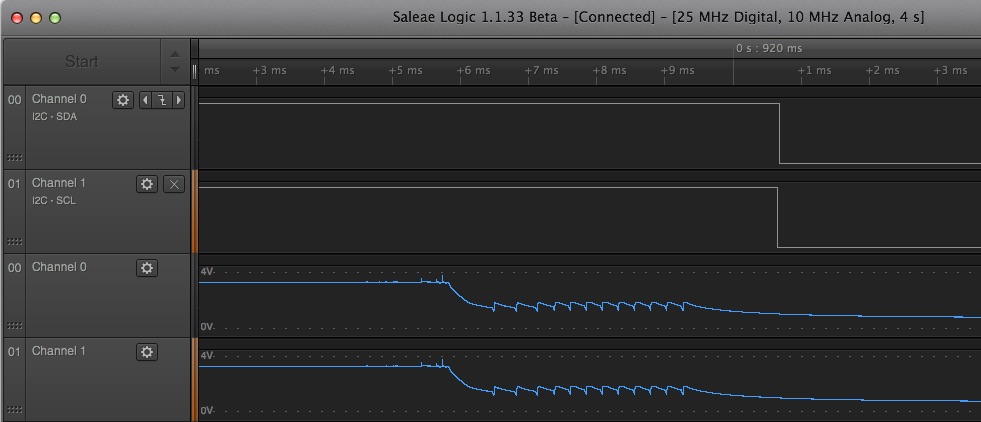
I tried to be smarter than the datasheet and put 2.7K in. It turned out, that they are two small to drive the SDA and SCL lines to GND fast enough. So use 4.7K for the TWI/I2Cs instead. For the X-Bus 2.7K seems to work, but the connection using a 20cm cable is much longer as the 1cm data lines on the board for the BMP180.
I got myself a Saleae Logic8 logic analyser. Why it is probably not the most needed tool, in this case it helps a lot. And it brings analog monitoring functionality as well. From the signal shape below I figured out that something goes wrong. The XMEGA trys to pull down the signal resulting in a slow drop of the signal voltage.
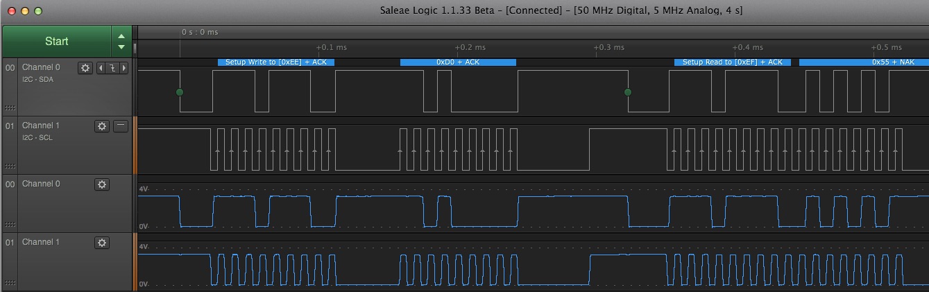
It has to look this way. The sequence just reads the static device ID for test purposes.
Initializing the Master
Here the code from the TWI initialization routine above again in short form:
 1 bool spektel_init() {
 2 // Initialize ports
 3 TWI_MASTER_PORT.PIN0CTRL = PORT_OPC_WIREDAND_gc;
 4 TWI_MASTER_PORT.PIN1CTRL = PORT_OPC_WIREDAND_gc;
 5 irq_initialize_vectors();
 6 sysclk_enable_peripheral_clock(&TWI_MASTER);
 7 twi_bridge_enable(&TWI_MASTER);
 8 twi_options_t m_options = {
 9 	.speed     = TWI_SPEED,
10 	.chip      = TWI_MASTER_ADDR,
11 	.speed_reg = TWI_BAUD(sysclk_get_cpu_hz(), TWI_SPEED)
12 };
Now we can directly start writing to the slave devices. In our case, the BMP180 provides EEPROM style registers for the communication. So this is a standard style for TWI communication.
Write: Write the 7-bit slave address and the LSB (most right bit) bit 1 for read and 0 for
write. As it turns out this was the next pitfall the ASF provides for me. In all of the
Atmel code, I worked with the 7-bit slave address more or less like with an 8-bit address
(expect for direct access to the registers). But the ASF library functions
twi_master_writeand twi_master_read add the LSB dependent on the read or write function.
I guess this is part of the TWI-EEPROM access protocol. Where the Bosch datasheet talks
about 0xEF for read and 0xEE for write, the ASF functions need 0x77! With this we can read
and write bytes:
Here the code from the TWI initialization routine above again in short form:
 1 /** Read a byte
 2  *
 3  * \param reg_addr the register address.
 4  * \param byte the data to be read.
 5  *
 6  * \return status of read operation
 7  */
 8 static uint8_t read_byte(const uint8_t reg_addr, uint8_t *byte)
 9 {
10 	twi_package_t r_packet = {
11 		.addr		 = { reg_addr },
12 		.addr_length = 1,
13 		.chip        = BMP180_ADDR_READ >> 1,
14 		.buffer      = byte,
15 		.length      = 1,
16 		.no_wait     = false
17 	};
18 	return twi_master_read(&TWI_MASTER, &r_packet);
19 }
20
21 /** Write a byte
22  *
23  * \param reg_addr the register address.
24  * \param byte the data to be written.
25  *
26  * \return status of operation
27  */
28 static uint8_t write_byte(const uint8_t reg_addr, uint8_t byte)
29 {
30 	twi_package_t w_packet = {
31 		.addr		 = { reg_addr },
32 		.addr_length = sizeof(reg_addr),
33 		.chip        = BMP180_ADDR_WRITE >> 1,
34 		.buffer      = &byte,
35 		.length      = sizeof(uint8_t),
36 		.no_wait     = false
37 	};
38
39 	return twi_master_write(&TWI_MASTER, &w_packet);
40 }
For the .chip you can use 0x77 or the datasheet address shifted to the right. On the bus the XMEGA will call with 0xEF and 0XEF showing if it wants to read or write.
Reading many bytes
Another pitfall was, that the Atmel ASF seems to expect the MSB (in this case higher byte
of a 16 bit value) and LSB (lower byte) order different than the Bosch BMP180. The
library supports to read multiple bytes in one read. Doing so, the BMP180 respondes with
the MSB, the Master sends an ACK requesting more data. Then the BMP180 sends the LSB
and a NAK follows to finish the communication and release the bus.
But the ASF gives back that values in the wrong order LSB-MSB. So a swap operation is needed
at the end. Either the BMP180 or the ASF gets it wrong!?
 1 /** Read word (16bit)
 2  *
 3  * \param reg_addr the register address.
 4  * \param word the data to be read.
 5  *
 6  * \return status of operation
 7  */
 8 static uint8_t read_word(const uint8_t reg_addr, uint16_t *word)
 9 {
10 	uint8_t err;
11
12 	twi_package_t r_packet = {
13 		.addr		 = { reg_addr },
14 		.addr_length = sizeof(reg_addr),
15 		.chip        = BMP180_ADDR_READ >> 1,
16 		.buffer      = word,
17 		.length      = sizeof(uint16_t),
18 		.no_wait     = false
19 	};
20 	err = twi_master_read(&TWI_MASTER, &r_packet);
21
22 	uint8_t lsb = (*word) >> 8;
23 	(*word) = ((*word) << 8) | lsb;
24
25 	return err;
26 }